教程 6:四轮机器人(60 分钟)
本教程旨在从零开始创建你的第一个机器人。 该机器人将由一个本体、四个车轮和两个距离传感器组成。 最终结果如此图所示。 下图展示了机器人的俯视图。
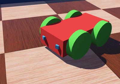
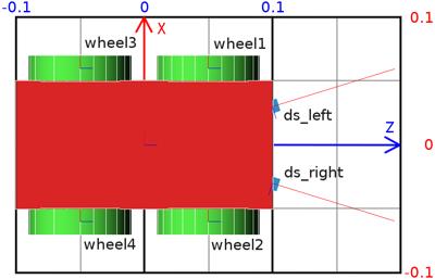
新仿真
动手实践 #1:将上一个教程的世界文件另存为
4_wheeled_robot.wbt。 删除定义 e-puck、球、哑铃以及接触属性的节点。 保留地面、墙壁和灯光。
将机器人拆分为 Solid 节点
创建机器人模型时的一些定义和规则:
包含 [Solid(https://cyberbotics.com/doc/reference/solid) 节点及其所有派生节点的集合称为 solid 节点。
对于 [Device(https://cyberbotics.com/doc/reference/device)、[Robot(https://cyberbotics.com/doc/reference/robot)、[Joint(https://cyberbotics.com/doc/reference/joint) 和 [Motor(https://cyberbotics.com/doc/reference/motor) 节点,也适用类似的定义。 你可以在[节点图表(https://cyberbotics.com/doc/reference/node-chart)中获取更多有关节点层次结构的信息。
大多数传感器和执行器同时也是 [Solid(https://cyberbotics.com/doc/reference/solid) 节点和 [Device(https://cyberbotics.com/doc/reference/device) 节点。
[Robot(https://cyberbotics.com/doc/reference/robot) 模型的主要结构是由相互链接的 [Solid(https://cyberbotics.com/doc/reference/solid) 节点构成的一棵树。 这棵树的根节点应当是一个 [Robot(https://cyberbotics.com/doc/reference/robot) 节点。
solid 节点之间通过 [Joint(https://cyberbotics.com/doc/reference/joint) 节点相互链接。 [Device(https://cyberbotics.com/doc/reference/device) 节点应当是 [Robot(https://cyberbotics.com/doc/reference/robot) 节点、[Solid(https://cyberbotics.com/doc/reference/solid) 节点或 [Joint(https://cyberbotics.com/doc/reference/joint) 节点的直接子节点。
[Joint(https://cyberbotics.com/doc/reference/joint) 节点用于在其父节点与子节点之间添加一个(或两个)自由度(DOF)。 [Joint(https://cyberbotics.com/doc/reference/joint) 节点的直接父节点和直接子节点都是 [Solid(https://cyberbotics.com/doc/reference/solid) 节点。
派生自 [Joint(https://cyberbotics.com/doc/reference/joint) 的节点可以在相互链接的 [Solid(https://cyberbotics.com/doc/reference/solid) 节点之间创建不同类型的约束。 机器人学中最常用的是 [HingeJoint(https://cyberbotics.com/doc/reference/hingejoint),可用于模拟(amongst others)旋转电机,包括车轮。
通过分别向 [Joint(https://cyberbotics.com/doc/reference/joint) 节点的
device字段添加 [PositionSensor(https://cyberbotics.com/doc/reference/positionsensor) 节点或电机节点,即可对其进行监测或驱动。
记住这些规则之后,我们就可以开始设计用于对机器人建模的节点层次结构了。 第一步是确定机器人的哪些部分应当被建模为 [Solid(https://cyberbotics.com/doc/reference/solid) 节点。
在我们的示例中,这一点相当明显。 该机器人有 4 个自由度,对应 4 个车轮电机。 它可以划分为五个 solid 节点:本体和四个车轮。
根据机器人模型的预期应用,建模时可能需要减少自由度以获得高效的仿真。 例如,以逼真的方式建模一个万向轮意味着要建模 2 个自由度。 但如果仿真并不需要这种精度,则可以找到更高效的方法。 例如,将万向轮建模为一个与地面摩擦系数为零的 [Sphere(https://cyberbotics.com/doc/reference/sphere)。
第二步是确定哪个 [Solid(https://cyberbotics.com/doc/reference/solid) 节点是 [Robot(https://cyberbotics.com/doc/reference/robot) 节点(即根节点)。 这一选择是任意的,但通常某个方案会容易实现得多。 例如,对于人形机器人,机器人节点通常是机器人的胸部,因为机器人的对称性有助于关节参数的计算。
在我们的例子中,本体的长方体(box)显然是更好的选择。 此图展示了机器人的 solid 节点层次结构。
动手实践 #2:在场景树的末尾,添加一个 [Robot(https://cyberbotics.com/doc/reference/robot) 节点,它拥有四个 [HingeJoint(https://cyberbotics.com/doc/reference/hingejoint) 节点,每个 [HingeJoint(https://cyberbotics.com/doc/reference/hingejoint) 节点拥有一个作为
endPoint的 [Solid(https://cyberbotics.com/doc/reference/solid) 节点。 请参考此图。 向 [Robot(https://cyberbotics.com/doc/reference/robot) 节点添加一个包含 Box 几何体的 [Shape(https://cyberbotics.com/doc/reference/shape) 节点。 将 [Shape(https://cyberbotics.com/doc/reference/shape) 的颜色设置为红色。 使用该 [Shape(https://cyberbotics.com/doc/reference/shape) 来定义 [Robot(https://cyberbotics.com/doc/reference/robot) 节点的boundingObject字段。 长方体的尺寸为(0.2, 0.1, 0.05)。 向 [Robot(https://cyberbotics.com/doc/reference/robot) 添加一个 [Physics(https://cyberbotics.com/doc/reference/physics) 节点。 此图表示了定义该机器人的所有节点。 到目前为止,只实现了根 [Robot(https://cyberbotics.com/doc/reference/robot) 节点的直接子节点。
graph TD
  Robot[Robot] -->|children| HingeJoint[HingeJoint]
    HingeJoint -->|endPoint| Solid[DEF WHEEL1 Solid]
  Robot -.->|children| OtherWheels[Other wheels]
  style HingeJoint fill:#ffe4bf;
class Robot highlightedNode;HingeJoint
车轮的初始位置由 [Solid(https://cyberbotics.com/doc/reference/solid) 节点的 translation(平移)和 rotation(旋转)字段定义。
旋转原点(anchor)和旋转轴(axis)由 [HingeJoint(https://cyberbotics.com/doc/reference/hingejoint) 节点可选的 [HingeJointParameters(https://cyberbotics.com/doc/reference/hingejointparameters) 子节点定义。
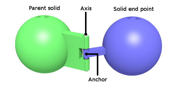
车轮的半径为 0.04,厚度(圆柱体的高度)为 0.02。
对于第一个车轮,[Solid(https://cyberbotics.com/doc/reference/solid) 的 translation 应定义为 (0.05, 0.06, 0),以定义本体与车轮之间的相对间隙,rotation 应定义为 (1 0 0 1.5708),以便正确放置车轮圆柱体的朝向。
[HingeJointParameters(https://cyberbotics.com/doc/reference/hingejointparameters) 的 anchor 也应定义为 (0.05, 0.06, 0),以定义旋转原点(相对于本体)。
最后,[HingeJointParameters(https://cyberbotics.com/doc/reference/hingejointparameters) 的 axis 应当定义旋转轴。
在我们的例子中,它沿 y 轴方向(即 (0, 1, 0))。
动手实践 #3:添加一个 [HingeJointParameters(https://cyberbotics.com/doc/reference/hingejointparameters) 节点,并按上述说明输入字段值。 对于其他车轮,有些正负号显然需要做相应更新。
现在,让我们实现车轮的圆柱体形状。
对于每个 [HingeJoint(https://cyberbotics.com/doc/reference/hingejoint),需要在三个字段中添加节点。
- jointParameters:添加一个 [HingeJointParameters(https://cyberbotics.com/doc/reference/hingejointparameters),并配置 anchor(0.05 -0.06 0)和 axis(0 1 0)字段。 这些值需要根据车轮的位置进行修改。
- device:添加一个 [RotationalMotor(https://cyberbotics.com/doc/reference/rotationalmotor),以便能够驱动车轮。根据[此图](#top-view-of-the-4-wheeled-robot-the-grid-behind-the-robot-has-a-dimension-of-0-2-x-0-3-meters-the-text-labels-correspond-to-the-name-of-the-device),将它们的
name字段依次设为wheel1到wheel4。 这些标签将用于在控制器中引用各个车轮。 - endPoint:添加一个 [Solid(https://cyberbotics.com/doc/reference/solid) 节点,然后在 [Solid(https://cyberbotics.com/doc/reference/solid) 的
children字段中添加一个 [Shape(https://cyberbotics.com/doc/reference/shape) 节点,最后在 [Shape(https://cyberbotics.com/doc/reference/shape) 节点的geometry字段中添加一个 [Cylinder(https://cyberbotics.com/doc/reference/cylinder)。 [Cylinder(https://cyberbotics.com/doc/reference/cylinder) 的radius应为0.04,height应为0.02。 将车轮的颜色设置为绿色。
动手实践 #4:补全缺少的节点,以获得与此图所示相同的结构。 不要忘了 [Physics(https://cyberbotics.com/doc/reference/physics) 节点。
graph TD
  Robot[Robot] -->|physics| Physics1[Physics]
  Robot -->|boundingObject| USEBODY[USE BODY]
  Robot -->|children| Shape1[DEF BODY Shape]
    Shape1 -->|geometry| Box[Box]
    Shape1 -.- USEBODY
  Robot -->|children| HingeJoint[HingeJoint]
    HingeJoint -->|device| RotationalMotor[RotationalMotor]
    HingeJoint -->|jointParameters| HingeJointParameters[HingeJointParameters]
    HingeJoint -->|endPoint| Solid[DEF WHEEL1 Solid]
      Solid -->|physics| Physics2[DEF WHEEL_PH Physics]
      Solid -->|boundingObject| USEWHEEL[USE WHEEL]
      Solid -->|children| Shape2[DEF WHEEL Shape]
          Shape2 -.- USEWHEEL
          Shape2 -->|geometry| Cylinder[Cylinder]
  Robot -.->|children| OtherWheels["Other wheels (using WHEEL and WHEEL_PH)"]

  style HingeJoint fill:#ffe4bf;
  class Robot highlightedNode;
class Shape1,USEBODY,USEWHEEL secondaryNode;传感器
[教程 4(tutorial-4-more-about-controllers.html) 中 e-puck 所使用的传感器与本节所使用的传感器并不相同。请注意它们的测量区间为 0 cm = 0 到 10 cm = 1000。
有关 lookupTable 字段的更多信息请见[这里(https://cyberbotics.com/doc/reference/distancesensor#lookup-table)。
机器人建模的最后一部分是向机器人添加两个距离传感器。 这可以通过添加两个作为 [Robot(https://cyberbotics.com/doc/reference/robot) 节点直接子节点的 [DistanceSensor(https://cyberbotics.com/doc/reference/distancesensor) 节点来实现。 注意,距离传感器沿其正 x 轴方向采集数据。 因此,必须旋转距离传感器,使其 x 轴指向机器人外部(参见此图)。
回顾:如何知道距离传感器的朝向?
正如[教程 3(tutorial-3-appearance.html)中已经提到的,可以使用快捷键 ctrl-F10 或 View / Optional Rendering / Show DistanceSensor Rays 来查看距离传感器的射线。
动手实践 #5:按照上述说明添加两个距离传感器。 距离传感器与机器人的前进向量成 0.3 [rad] 的夹角。 将图形形状和物理形状设置为未经变换的立方体,边长为
0.01[m]。 将颜色设置为蓝色。 根据此图中的标签设置name字段。
提示:如何精确设置距离传感器的朝向?
在 [DistanceSensor(https://cyberbotics.com/doc/reference/distancesensor) 节点中,rotation 字段有 4 个参数。如果将角度参数设置为 0,则可以使用鼠标滚轮以 0.1309 rad(= 7.5 度)为步长进行增量/减量调节。
控制器
在之前的教程中,你已经学习了如何设置反馈回路以及如何读取距离传感器的数值。 然而,驱动 [RotationalMotor(https://cyberbotics.com/doc/reference/rotationalmotor) 节点是全新的内容。 要对旋转电机进行编程,第一步是包含与 [RotationalMotor(https://cyberbotics.com/doc/reference/rotationalmotor) 节点对应的 API 模块:
#include <webots/motor.h>#include <webots/Motor.hpp>from controller import Motorimport com.cyberbotics.webots.controller.Motor;在 MATLAB 控制器中你不需要包含 API,Webots 会替你完成这件事。
然后获取 [RotationalMotor(https://cyberbotics.com/doc/reference/rotationalmotor) 节点的引用:
// initialize motors
WbDeviceTag wheels[4];
char wheels_names[4][8] = {
  "wheel1", "wheel2", "wheel3", "wheel4"
};
int i;
for (i = 0; i < 4 ; i++)
  wheels[i] = wb_robot_get_device(wheels_names[i]);
// initialize motors
Motor *wheels[4];
char wheelsNames[4][8] = {"wheel1", "wheel2", "wheel3", "wheel4"};
for (int i = 0; i < 4 ; i++)
wheels[i] = robot->getMotor(wheelsNames[i]);# initialize motors
wheels = []
wheelsNames = ['wheel1', 'wheel2', 'wheel3', 'wheel4']
for name in wheelsNames:
wheels.append(robot.getDevice(name))// initialize motors
Motor[4] wheels;
String[] wheelsNames = {"wheel1", "wheel2", "wheel3", "wheel4"};
for (int i = 0; i < wheelsNames.length; i++)
wheels[i] = robot.getMotor(wheelsNames[i]);% initialize motors
wheels = [];
wheels_names = [ "wheel1", "wheel2", "wheel3", "wheel4" ];
for i = 1:4
wheels(i) = wb_robot_get_device(convertStringsToChars(wheels_names(i)));
end可以通过设置 [Motor(https://cyberbotics.com/doc/reference/motor) 的位置、速度、加速度或力来驱动它。 这里我们感兴趣的是设置它的速度。 这可以通过将其位置设置为无穷大并对速度加以限制来实现:
double speed = -1.5; // [rad/s]
wb_motor_set_position(wheels[0], INFINITY);
wb_motor_set_velocity(wheels[0], speed);
double speed = -1.5; // [rad/s]
wheels[0]->setPosition(INFINITY);
wheels[0]->setVelocity(speed);speed = -1.5 # [rad/s]
wheels[0].setPosition(float('inf'))
wheels[0].setVelocity(speed)double speed = -1.5; // [rad/s]
wheels[0].setPosition(Double.POSITIVE_INFINIT);
wheels[0].setVelocity(speed);speed = -1.5; % [rad/s]
wb_motor_set_position(wheels(1), inf);
wb_motor_set_velocity(wheels(1), speed);动手实践 #6:实现一个名为
four_wheeled_collision_avoidance的控制器,驱动机器人移动,并通过距离传感器检测障碍物来避开它们。
注意,[DistanceSensor(https://cyberbotics.com/doc/reference/distancesensor) 节点的 lookupTable 字段指示了传感器返回的数值。
为便于借助传感器进行调试,可以在[机器人窗口(controller-plugin.html#robot-window)中实时查看传感器的数值。
要打开[机器人窗口(controller-plugin.html#robot-window),双击机器人本体,左侧将弹出一个菜单,其中包含 [DistanceSensor(https://cyberbotics.com/doc/reference/distancesensor) 和 [RotationalMotor(https://cyberbotics.com/doc/reference/rotationalmotor) 的曲线图。
运行仿真即可观察其变化过程。
别忘了设置 [Robot(https://cyberbotics.com/doc/reference/robot) 节点的 controller 字段,以指向你的新控制器。
像往常一样,本练习的一种可行解决方案位于 tutorials 目录中。
控制器代码
下面是上一小节中开发的控制器的完整代码。
#include <webots/distance_sensor.h>
#include <webots/motor.h>
#include <webots/robot.h>

int main(int argc, char **argv) {
  wb_robot_init();
  const int time_step = (int) wb_robot_get_basic_time_step();
  int i;
  bool avoid_obstacle_counter = 0;
  WbDeviceTag ds[2];
  char ds_names[2][10] = {"ds_left", "ds_right"};
  for (i = 0; i < 2; i++) {
    ds[i] = wb_robot_get_device(ds_names[i]);
    wb_distance_sensor_enable(ds[i], time_step);
  }
  WbDeviceTag wheels[4];
  char wheels_names[4][8] = {"wheel1", "wheel2", "wheel3", "wheel4"};
  for (i = 0; i < 4; i++) {
    wheels[i] = wb_robot_get_device(wheels_names[i]);
    wb_motor_set_position(wheels[i], INFINITY);
  }
  while (wb_robot_step(time_step) != -1) {
    double left_speed = 1.0;
    double right_speed = 1.0;
    if (avoid_obstacle_counter > 0) {
      avoid_obstacle_counter--;
      left_speed = 1.0;
      right_speed = -1.0;
    } else { // read sensors
      double ds_values[2];
      for (i = 0; i < 2; i++)
        ds_values[i] = wb_distance_sensor_get_value(ds[i]);
      if (ds_values[0] < 950.0 || ds_values[1] < 950.0)
        avoid_obstacle_counter = 100;
    }
    wb_motor_set_velocity(wheels[0], left_speed);
    wb_motor_set_velocity(wheels[1], right_speed);
    wb_motor_set_velocity(wheels[2], left_speed);
    wb_motor_set_velocity(wheels[3], right_speed);
  }
  wb_robot_cleanup();
  return 0;  // EXIT_SUCCESS
}#include <webots/DistanceSensor.hpp>
#include <webots/Motor.hpp>
#include <webots/Robot.hpp>
using namespace webots;
int main(int argc, char **argv) {
Robot *robot = new Robot();
int timeStep = (int)robot->getBasicTimeStep();
DistanceSensor *ds[2];
char dsNames[2][10] = {"ds_right", "ds_left"};
for (int i = 0; i < 2; i++) {
ds[i] = robot->getDistanceSensor(dsNames[i]);
ds[i]->enable(timeStep);
}
Motor *wheels[4];
char wheels_names[4][8] = {"wheel1", "wheel2", "wheel3", "wheel4"};
for (int i = 0; i < 4; i++) {
wheels[i] = robot->getMotor(wheels_names[i]);
wheels[i]->setPosition(INFINITY);
wheels[i]->setVelocity(0.0);
}
int avoidObstacleCounter = 0;
while (robot->step(timeStep) != -1) {
double leftSpeed = 1.0;
double rightSpeed = 1.0;
if (avoidObstacleCounter > 0) {
avoidObstacleCounter--;
leftSpeed = 1.0;
rightSpeed = -1.0;
} else { // read sensors
for (int i = 0; i < 2; i++) {
if (ds[i]->getValue() < 950.0)
avoidObstacleCounter = 100;
}
}
wheels[0]->setVelocity(leftSpeed);
wheels[1]->setVelocity(rightSpeed);
wheels[2]->setVelocity(leftSpeed);
wheels[3]->setVelocity(rightSpeed);
}
delete robot;
return 0; // EXIT_SUCCESS
}from controller import Robot
robot = Robot()
timestep = int(robot.getBasicTimeStep())
ds = []
dsNames = ['ds_right', 'ds_left']
for i in range(2):
ds.append(robot.getDevice(dsNames[i]))
ds[i].enable(timestep)
wheels = []
wheelsNames = ['wheel1', 'wheel2', 'wheel3', 'wheel4']
for i in range(4):
wheels.append(robot.getDevice(wheelsNames[i]))
wheels[i].setPosition(float('inf'))
wheels[i].setVelocity(0.0)
avoidObstacleCounter = 0
while robot.step(timestep) != -1:
leftSpeed = 1.0
rightSpeed = 1.0
if avoidObstacleCounter > 0:
avoidObstacleCounter -= 1
leftSpeed = 1.0
rightSpeed = -1.0
else: # read sensors
for i in range(2):
if ds[i].getValue() < 950.0:
avoidObstacleCounter = 100
wheels[0].setVelocity(leftSpeed)
wheels[1].setVelocity(rightSpeed)
wheels[2].setVelocity(leftSpeed)
wheels[3].setVelocity(rightSpeed)import com.cyberbotics.webots.controller.Robot;
import com.cyberbotics.webots.controller.DistanceSensor;
import com.cyberbotics.webots.controller.Motor;
public class FourWheelsCollisionAvoidance {
public static void main(String[] args) {
Robot robot = new Robot();
int timeStep = (int) robot.getBasicTimeStep();
DistanceSensor[] ds = new DistanceSensor[2];
String[] dsNames = {"ds_right", "ds_left"};
for (int i = 0; i < 2; i++) {
ds[i] = robot.getDistanceSensor(dsNames[i]);
ds[i].enable(timeStep);
}
Motor[] wheels = new Motor[4];
String[] wheelsNames = {"wheel1", "wheel2", "wheel3", "wheel4"};
for (int i = 0; i < 4; i++) {
wheels[i] = robot.getMotor(wheelsNames[i]);
wheels[i].setPosition(Double.POSITIVE_INFINITY);
wheels[i].setVelocity(0.0);
}
int avoidObstacleCounter = 0;
while (robot.step(timeStep) != -1) {
double leftSpeed = 1.0;
double rightSpeed = 1.0;
if (avoidObstacleCounter > 0) {
avoidObstacleCounter--;
leftSpeed = 1.0;
rightSpeed = -1.0;
} else { // read sensors
for (int i = 0; i < 2; i++) {
if (ds[i].getValue() < 950.0)
avoidObstacleCounter = 100;
}
}
wheels[0].setVelocity(leftSpeed);
wheels[1].setVelocity(rightSpeed);
wheels[2].setVelocity(leftSpeed);
wheels[3].setVelocity(rightSpeed);
}
}
}function four_wheeled_collision_avoidance
TIME_STEP = wb_robot_get_basic_time_step();
ds = [];
ds_names = [ "ds_right", "ds_left" ];
for i = 1:2
ds(i) = wb_robot_get_device(convertStringsToChars(ds_names(i)));
wb_distance_sensor_enable(ds(i), TIME_STEP);
end
wheels = [];
wheels_names = [ "wheel1", "wheel2", "wheel3", "wheel4" ];
for i = 1:4
wheels(i) = wb_robot_get_device(convertStringsToChars(wheels_names(i)));
wb_motor_set_position(wheels(i), inf);
wb_motor_set_velocity(wheels(i), 0.0);
end
avoid_obstacle_counter = 0;
while wb_robot_step(TIME_STEP) ~= -1
left_speed = 1.0;
right_speed = 1.0;
if avoid_obstacle_counter > 0
avoid_obstacle_counter = avoid_obstacle_counter - 1;
left_speed = 1.0;
right_speed = -1.0;
else % read sensors
for i = 1:2
if wb_distance_sensor_get_value(ds(i)) < 950.0
avoid_obstacle_counter = 100;
end
end
end
wb_motor_set_velocity(wheels(1), left_speed);
wb_motor_set_velocity(wheels(2), right_speed);
wb_motor_set_velocity(wheels(3), left_speed);
wb_motor_set_velocity(wheels(4), right_speed);
% if your code plots some graphics, it needs to flushed like this:
drawnow;
end解决方案:世界文件
要将你的世界文件与解决方案进行对比,请在你的文件中找到[教程 1(tutorial-1-your-first-simulation-in-webots.html)中创建的名为 "my_first_simulation" 的文件夹,然后进入 "worlds" 文件夹,并使用文本编辑器打开相应的世界文件。 本解决方案与其他解决方案一样,位于解决方案目录中。
结论
现在,你已经能够设计简单的机器人模型、实现它们并为其创建控制器。
更具体地说,你学习了机器人模型设计所涉及的各种节点、将一个 solid 相对于另一个 solid 进行平移和旋转的方法,以及控制器驱动旋转电机的方式。